The Metallurgy and Geometry of Finned Tube Rolling Blades: A B2B Manufacturing Guide
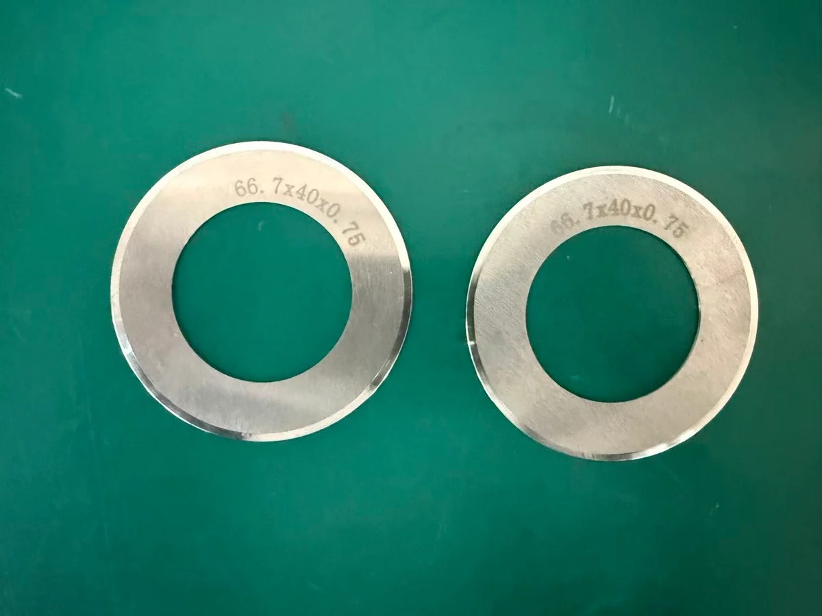
An engineering-depth guide to selecting and configuring Copper, Aluminum, and Stainless Steel finned tube rolling blades. Optimize tool life, prevent galling, and maximize heat exchanger thermal efficiency.
In B2B heat exchanger manufacturing, production efficiency and thermal performance are dictated by the quality of your extruded finned tubes. The cold-rolling process—where a series of rotating rolling blades (also known as finning discs) plasticize and extrude fins directly from the tube wall—demands absolute precision from your tooling.
For plant managers, B2B procurement officers, and tooling engineers, selecting the correct finned tube rolling blades is not merely a purchasing decision; it is a critical engineering variable. Mismatched blade metallurgy, incorrect flank angles, or poor arbor assembly calibration will result in rapid tool wear, fin profile distortion, and costly production downtime.
This technical guide analyzes the metallurgical and geometric principles required to optimize your rolling processes for Copper, Aluminum, and Stainless Steel finned tubes.
1. Metallurgical Selection: Matching Tool Steels to Tube Alloys
The mechanical deformation of tube alloys under high pressure generates intense localized heat and friction. To maintain dimensional integrity, rolling blades must be fabricated from premium tool steels that match the physical properties of the target tube material.
A. Copper Finned Tube Rolling Blades
Copper alloys (e.g., C12200 phosphorus-deoxidized copper) are highly ductile but prone to adhesive wear (galling). Under rolling pressure, micro-particles of copper tend to cold-weld onto the blade flanks, leading to torn fins and ruined profiles.
- Optimal Tooling Material: High-Speed Steel (HSS) grades such as M2 (1.3343) or M35 (1.3243) with Cobalt content.
- Surface Treatment: High-mirror polishing (Ra < 0.1 μm) combined with a TiAlN (Titanium Aluminum Nitride) or CrN (Chromium Nitride) PVD coating. This reduces the coefficient of friction and prevents copper adhesion.
- Hardness Specification: 61 – 63 HRC to balance wear resistance with fracture toughness.
B. Aluminum Finned Tube Rolling Blades
Aluminum (typically 1060 or 6063 alloys) is soft and flows easily, but it is extremely sticky. The primary B2B manufacturing challenge is preventing aluminum accumulation in the gullets of the rolling discs.
- Optimal Tooling Material: Vacuum-degassed HSS or specialized cold-work tool steels like D2 (1.2379).
- Surface Treatment: Super-finished flanks with specialized anti-friction coatings. Polishing is critical; any micro-scratch on the blade surface acts as an anchor point for aluminum buildup.
- Hardness Specification: 60 – 62 HRC.
C. Stainless Steel Finned Tube Rolling Blades
Stainless steel alloys (e.g., Grade 304, 316, or Duplex steels) possess high tensile strength and work-harden rapidly. The rolling forces required are up to 300% higher than those for copper, causing severe compressive stress on the blade tips.
- Optimal Tooling Material: Premium Powder Metallurgy (PM) Steels (e.g., ASP 2030, ASP 2060, or CPM Rex series) or high-alloy HSS like M42 (1.3247). PM steels feature an ultra-fine, homogeneous carbide distribution that prevents chipping under extreme loads.
- Heat Treatment: Double-vacuum hardening followed by triple tempering and sub-zero cryogenic treatment (-196°C) to eliminate residual austenite and maximize dimensional stability.
- Hardness Specification: 63 – 66 HRC to resist plastic deformation of the blade tip.
2. Geometric Design: Engineering the Perfect Fin Profile
The profile of the rolling blade determines the shape, height, and density of the resulting fins. The three most critical geometric variables are:
- Tip Radius: The point of initial penetration into the tube wall. A radius that is too sharp scores the core, while one that is too blunt increases the required radial force.
- Flank Angle: The slope that controls the extrusion force and tube ejection.
- Root Land: The flat section at the base of the blade that calibrates the spacing between adjacent fins.
Flank Angle Selection
- Sharp Angles (20° – 24°): Ideal for copper and aluminum. Reduces the required rolling torque and allows for high-density fin configurations (up to 36 FPI).
- Obtuse Angles (25° – 30°): Required for stainless steel. A wider angle increases the mechanical support behind the blade tip, preventing lateral flexing and chipping under high load.
Tip Radius Calibration
- Too Sharp (< 0.08 mm): Acts as a stress riser, scoring the tube core and creating micro-fractures that compromise the pressure-containing boundary of the tube.
- Too Blunt (> 0.25 mm): Drastically increases the radial rolling force, causing the tube to slip on the arbors and generating excessive heat that softens the tooling.
- NEXMEK Standard: CNC-ground tip radii held within a tolerance of ±0.005 mm to ensure smooth, uniform metal displacement.
3. Arbor Assembly and Spacing Calibration
High-performance tooling is only as good as its assembly. Extruded finned tubes are manufactured using three arbors positioned 120° apart. Each arbor holds a progressive “gang” of blades separated by precision spacer collars.
The assembly progresses in three distinct stages:
- Entry Stage (Forming): Small, sharp blades make the initial score in the tube wall.
- Middle Stage (Extruding): Medium, tapered blades progressively push the metal upward to form the fins.
- Exit Stage (Calibrating): Large, finished blades calibrate the final height and thickness of the fins.
To ensure consistent fin height and pitch:
- Spacer Tolerance: Spacing collars must be ground parallel within ±0.002 mm. Cumulative pitch error across a 50-blade arbor assembly must not exceed 0.02 mm.
- Progressive Loading: The blade diameters must increase progressively.
- Coolant Delivery: An abundant, continuous flow of sulfur-free, high-viscosity neat cutting oil or specialized synthetic emulsion must be directed precisely at the deformation zone to flush out micro-debris and control thermal expansion.
B2B Procurement: Why Precision Tooling Lowers TCO
For high-volume heat exchanger manufacturers, B2B procurement decisions should be based on the Total Cost of Ownership (TCO) rather than the initial purchase price of the blades.
| Tooling Quality Indicator | Low-Grade Import Blades | NEXMEK Premium Blades |
|---|---|---|
| Raw Material | Standard recycled scrap steel | Virgin Powder Metallurgy / Premium HSS |
| Thickness Tolerance | ±0.02 mm (leads to pitch drift) | ±0.003 mm (ensures pitch consistency) |
| Average Tool Lifetime | 8,000 to 12,000 meters (Copper) | 25,000 to 35,000 meters (Copper) |
| Fin Profile Accuracy | Degrades quickly; high reject rate | Consistent thermodynamic profile |
| Downtime Cost | High (frequent blade changes) | Minimal (maximized production runs) |
Partner with B2B Manufacturing Experts
NEXMEK is a leading B2B manufacturer of high-precision industrial tooling, specializing in premium rolling blades for the global heat exchanger and HVAC industries. Operating from our state-of-the-art facility in Shanghai, we combine advanced metallurgy, vacuum heat treatment, and ultra-precision CNC grinding to deliver blades that maximize your production uptime and ensure the thermal efficiency of your products.
Contact our engineering team today to discuss your arbor configurations, request technical drawings, or receive a B2B quotation.
Recursos relacionados
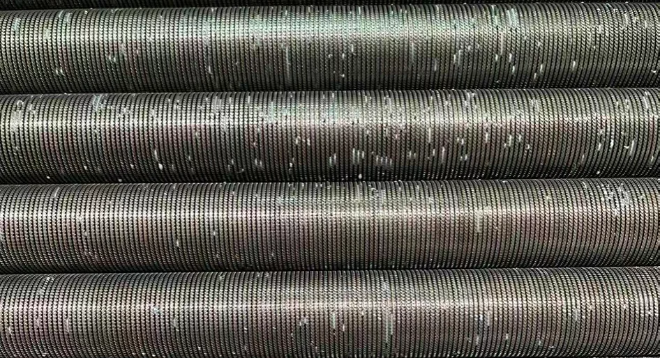
The Role of Precision Rolling Tools in Maximizing Heat Exchanger Thermal Efficiency
Discover how the micro-geometric precision of finned tube rolling blades directly determines heat transfer coefficients and prevents thermal contact resistance in industrial heat exchangers.
Industrial Shear Blades for Container Glass Manufacturing: Optimizing Lifetime and Cut Quality
Learn how premium tungsten carbide metallurgy, precise blade tensioning, and optimized shear spray lubrication prevent defects and extend shear blade lifetime in high-volume glass manufacturing.
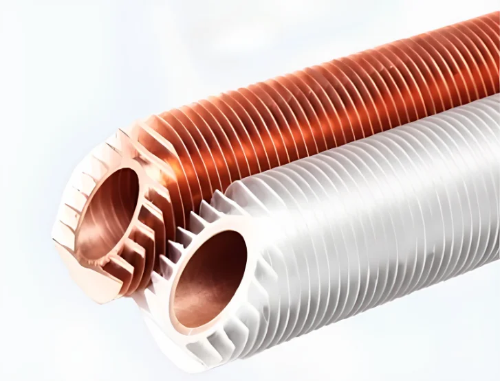
Optimizing Copper Finned Tube Extrusion: Metallurgical Integrity and Anti-Galling Tooling Design
Explore the mechanics of copper finned tube extrusion, including PVD coatings, cold-welding prevention, and arbor calibration to maximize tooling lifespan.